Flexible circuits are known for their versatility. They can be folded, bent, and twisted into a variety of configurations. The success of a flex circuit is understanding that the design rules are different from a rigid circuit. The designers and engineers have to keep certain points in mind when creating a flex PCB to ensure success. We provide a few tips in this post.
Tips for Flex PCB Design Success
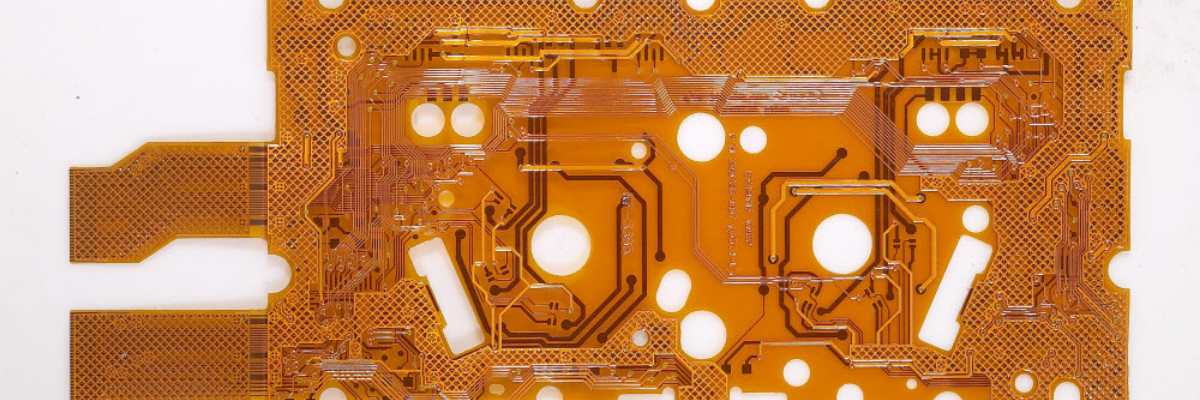
Let’s say you are designing a 2 layer flex PCB. If you are not too careful you may produce a PCB with many errors. Here are a few points you can perform to make your flex circuit board robust, and ready for production.
- Ensure Large Pad and Hole Sizes: Flexible material is easy to drill during the design process. Hence, when creating flex PCBs, the hole and pad sizes should be 10 mils at minimum. For the plating process, only use barrel size plates for the pads. The flex holes should not be plated to ensure flexibility. Also, by not plating the flex holes, it becomes easier to keep electrodeposited copper off of the PCB surface.
- Flexibility for Stiffeners and Coverfilms: Flexible circuitry is exposed during processes like copper plating, etching, and pumice scrubbing during fabrication. This can lead to certain dimensional changes. Designing flexible circuitry requires large tolerances to allow for stiffeners, and coverfilms. Also, when considering coverfilms, you also have to take the adhesive squeezing out when the film dielectric is laminated. If not performed, the fabrication and inspection processes will become very difficult. Hence, you should give allow more room for the coverfilm in a flex design.
- Create Hashed Ground Planes: Many industrial applications require the use of multilayer flex PCBs. However, the problem here is, when the layers are increased to 10 or 12, it becomes difficult for the PCB to bend and flex. A good way to solve this problem is to use hashed ground planes on both sides of the signal layers.
- Smooth Radius Layout to Prevent Stress Points: As flex circuits are used in dynamic applications, you require specialized trace configurations. This means that trace configurations used for rigid circuits cannot be used. If used, the traces with sharp corners can become stress points. Hence, ensure that the layout has a smooth radius for turn points. Also, attach stiffeners only at select places to prevent bending of soldered areas.
- Create Fixture for Assembly: The assembly of flex PCBs can be difficult as they are not sturdy due to the flex material. This problem can be solved by creating specialized fixtures, which provide the right amount of backing to allow for easy PCB assembly.
By keeping such tips in mind, it may be possible to improve the flex PCB design process, and ensure the delivery of industrial grade circuit board products. If you are looking for 2 layer flex PCBs, or other types, you can contact Rigiflex Technology, Inc.