As the name implies, rigid-flex PCBs are manufactured with the combination of both rigid and flexible circuit boards. These two boards are permanently connected together to form PCBs of various types.
Designing and manufacturing rigid-flex PCBs involve several steps. All these steps must be carried out with precision to produce a quality board.
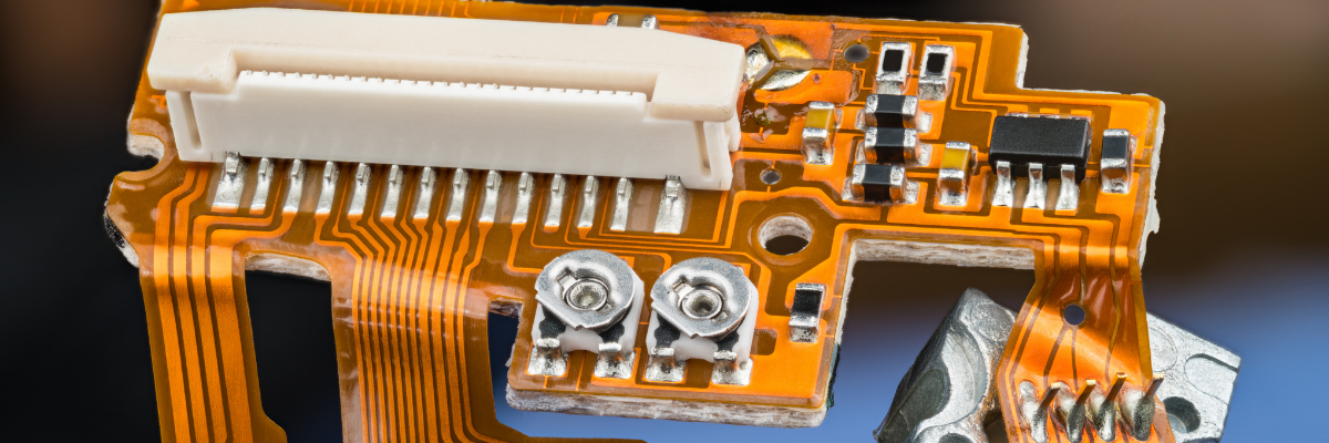
Steps in Rigid Flex Manufacturing
The major steps involved in rigid-flex manufacturing process are as follows:
- Apply Adhesive/Coating on Copper Layer – The first and foremost step in the rigid-flex PCB manufacturing involves applying suitable adhesives (choose between epoxy or acrylic adhesives) on a thin copper layer.
- Add Copper Foil– A thin layer of copper foil is added onto the adhesives using processes such as lamination or chemical plating.
- Drilling– Ultra-small to medium to large sized holes are mechanically drilled into the flex substrate. Advancements in technology allow for laser drilling in the flex platform to create small to large holes. Excimer (ultraviolet) or YAG (Infrared) lasers, and CO2 lasers are used to achieve a high level of accuracy.
- Plating Through-Hole – This is a crucial step in rigid-flex PCB manufacturing as it requires extreme care and accuracy. Once the holes are drilled on the flex platform, copper is deposited into them. Once this has been completed, the copper is chemically plated. Usually, manufacturers set the through-hole plating thickness as 1 mil and sometimes it is set as half mil.
- Coating Etch-Resist – Through-hole plating is followed by photosensitive etch-resist coating onto the flex surface. LPI (Liquid Photo Imageable) is ideal for this purpose. It can be applied by roller coat, spray, or curtain coat methods.
- Etching and Stripping – Once the copper film is etched, the etch-resist is chemically stripped from the circuit board.
- Coverlay Layers – Overlay, which acts as a solder mask, is applied on the top and bottom areas of the flex circuit to provide absolute protection to PCBs. One of the commonly used overlay materials is polyimide film with adhesive.
- Cutting the Flex – This step, which involves cutting the flex, is also known as blanking. Processess such as hydraulic punch and die set are used for cutting the flex. These methods allow for cutting several circuit boards simultaneously. To achieve cost-effectiveness, a blanking knife is used to cut the flex with precision.
- Lamination – After the blanking process, the flex circuit is laminated between the rigid sections. A thin and flexible lamination can be made using PI and glass.
The laminated flex circuit is then electrically tested to ensure its efficiency and performance.
A standardized manufacturing process following IPC (Association Connecting Electronics Industries) guidelines guarantees a reliable and economical rigid-flex PCB.