Flex circuits are designed to provide electrical connectivity in applications where space constraints, weight reduction, and mechanical flexibility are critical. However, certain areas of a flexible printed circuit require additional support to withstand assembly processes, connector insertion forces, component mounting requirements, and long-term mechanical stress. This is where a flex circuit stiffener becomes essential.
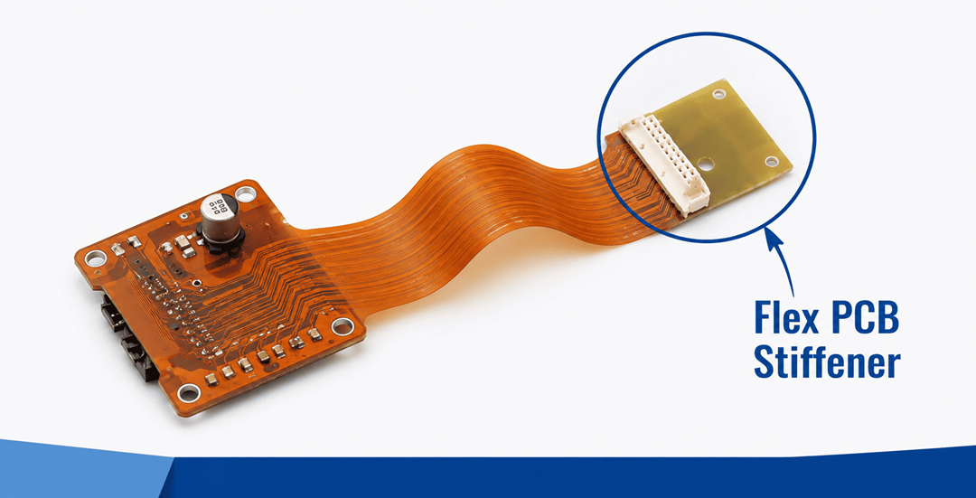
Flex PCB Stiffener
A flex circuit stiffener is a reinforcing material laminated or bonded to specific areas of a flexible PCB to provide localized rigidity. By reinforcing specific sections of a flexible circuit without compromising overall flexibility, stiffeners improve structural stability, assembly reliability, and product durability. Choosing the right flex PCB stiffener and its material is a critical design decision that directly impacts manufacturing efficiency, component performance, and product lifespan. This post explains flex PCB stiffeners, commonly used materials, and the factors that influence their selection.
What is a Flex PCB Stiffener?
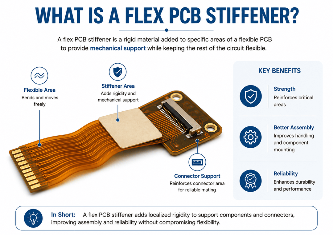
A flex PCB stiffener is a reinforcing material attached to specific areas of a flexible printed circuit board (PCB) to add mechanical support while keeping the rest of the circuit flexible. It is commonly used under connectors, components, and other high-stress areas to improve strength, assembly, and reliability.
Common flex PCB stiffener materials include polyimide, FR4, and stainless steel. The right material depends on the required rigidity, thickness, operating environment, and application. Selecting the correct flex circuit stiffener helps improve product durability, manufacturing efficiency, and long-term performance.
Common Reasons for Using a Flex PCB Stiffener
Unlike rigid-flex constructions that incorporate rigid board sections, stiffeners are added only where additional mechanical support is required.
- Connector Support: Stiffeners reinforce areas where connectors are inserted or removed repeatedly, preventing excessive flexing and reducing the risk of damage during mating cycles.
- SMT Component Support: Surface-mount components require a stable mounting platform during assembly and operation. Stiffeners help minimize board movement and improve solder joint reliability.
- Assembly Handling: Flexible circuits can be difficult to process during automated manufacturing. Stiffeners improve handling characteristics during pick-and-place, soldering, testing, and inspection processes.
- Mechanical Reinforcement: Areas exposed to repeated stress, pressure, or external forces benefit from additional structural support provided by stiffeners.
By reinforcing only targeted areas, designers can maintain the flexibility of the circuit while improving durability and manufacturability.
Flex PCB Stiffener Materials and Their Applications
The selection of a flex PCB stiffener material directly influences mechanical stability, assembly performance, connector support, and long-term reliability. The most commonly used stiffener materials include polyimide, FR4, and stainless steel, each offering distinct advantages for specific applications.
-
Polyimide Stiffeners:
Polyimide is widely used in thin, lightweight, and space-constrained designs where maintaining flexibility is important. Its key benefits include low weight, excellent thermal resistance, and compatibility with flexible circuit constructions. However, it provides less rigidity than FR4 and may not be suitable for applications requiring significant mechanical support.
-
FR4 Stiffeners:
FR4 is a popular choice for connector areas, SMT component mounting regions, and automated assembly processes. It offers excellent rigidity, dimensional stability, and assembly support, making it suitable for many commercial and industrial applications. The primary limitation is reduced flexibility and higher weight compared to polyimide.
-
Stainless Steel Stiffeners:
Stainless steel is used in applications that require maximum strength and durability, such as industrial electronics, aerospace systems, and high-vibration environments. It provides superior mechanical stability and resistance to shock and vibration. However, it increases weight, manufacturing complexity, and material costs while limiting flexibility in reinforced areas.
Key Factors to Consider When Choosing a Flex PCB Stiffener
Selecting the appropriate flex PCB stiffener requires evaluating several design, manufacturing, and operational factors to ensure reliability, durability, and assembly efficiency.
- Application Requirements: The intended application influences stiffener selection. Factors such as product function, operating environment, expected lifespan, and reliability requirements should be considered. For example, consumer electronics often prioritize lightweight designs, while industrial systems may require greater mechanical reinforcement.
- Component and Connector Support Needs: Connectors and components place mechanical demands on a flex circuit. Areas with large connectors, heavy components, or high component density may require additional support to maintain dimensional stability and improve solder joint reliability.
- Required Thickness: Stiffener thickness affects both mechanical performance and assembly compatibility. Designers must consider connector specifications, assembly requirements, and overall circuit stack-up to ensure proper fit and functionality.
- Flexibility vs. Rigidity Requirements: A balance between flexibility and reinforcement is essential. Areas intended for movement should retain flexibility, while connector and component mounting regions may require greater rigidity for stability and reliability.
- Assembly Process Requirements: Manufacturing processes such as pick-and-place assembly, soldering, testing, and inspection can influence stiffener selection. The right stiffener helps improve handling and supports consistent production quality.
- Environmental and Mechanical Stress Conditions: Exposure to temperature changes, vibration, mechanical shock, humidity, and other environmental factors can impact long-term performance. Applications in automotive, aerospace, and industrial sectors often require more robust reinforcement solutions.
- Weight and Space Constraints: Compact devices such as wearables and portable electronics often benefit from lightweight stiffener materials that support miniaturized designs without adding unnecessary bulk.
- Cost vs. Performance Considerations: Material selection should balance performance requirements with manufacturing costs. The most suitable stiffener provides the necessary mechanical support, reliability, and manufacturability while remaining cost effective for the intended application.
Optimize Your Flex Circuit Design with the Right Stiffener Expertise
As an OEM, if you require advice on flex PCB stiffeners or any stage of the PCB manufacturing process, ensure you connect with an experienced PCB assembly service provider.
Rigiflex Technology provides custom flex and rigid-flex PCB solutions backed by experienced engineering support, helping customers identify the most effective flex circuit stiffener for their specific design requirements. Contact our team today to discuss your project and optimize your flex circuit design for performance, durability, and manufacturability.
Frequently Asked Questions (FAQs)
How are flex circuit stiffeners attached to the PCB?
Stiffeners are typically bonded to the flex circuit using heat-activated or pressure-sensitive adhesives. The attachment method depends on the stiffener material, circuit construction, and application requirements.
Can a stiffener be applied to both sides of a flex circuit?
Yes. In some designs, stiffeners may be added to both sides of the flex circuit to achieve specific thickness requirements, improve structural balance, or provide additional support for connectors and components.
Do stiffeners impact the bend radius of a flex circuit?
Yes. Stiffeners increase rigidity in reinforced areas and should not be placed within intended bend regions. Designers must account for stiffener placement when determining minimum bend radius requirements.
How do designers determine the correct stiffener thickness?
The required thickness is typically determined by connector specifications, assembly requirements, component support needs, and overall circuit stack-up dimensions. Proper thickness selection helps ensure reliable assembly and mechanical performance.
Can stiffeners help improve automated assembly efficiency?
Yes. Stiffeners provide a more stable structure for handling during pick-and-place assembly, soldering, testing, and inspection processes, which can improve manufacturing consistency and reduce defects.