Flexible PCBs are increasingly used across industries where conventional rigid circuit boards cannot meet the demands of space, weight, form factor, or mechanical flexibility. Aerospace, medical, automotive, telecommunications, industrial, and consumer electronics are adopting flex circuits for compact designs, complex interconnections, and applications requiring circuits to conform to specific geometries. However, manufacturing a flexible PCB involves more than adapting the fabrication methods used for rigid boards.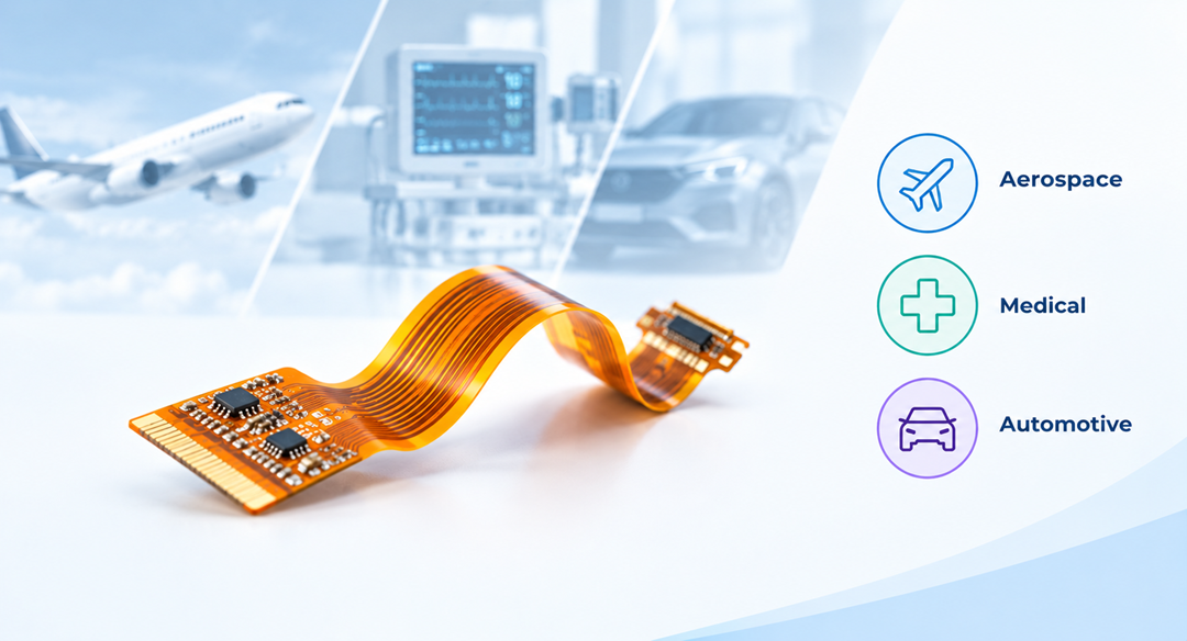
Material selection, copper type, layer configuration, bend requirements, coverlay, stiffeners, and testing must be considered based on how and where the circuit will operate. So, how are flexible PCBs manufactured for different applications? The answer depends on the performance requirements of the product. This post examines how flex PCB manufacturing considerations vary across aerospace, medical, and automotive electronics.
What Is a Flex PCB and Why Is It Used in Demanding Electronics?
A flex PCB is a circuit built on a flexible dielectric substrate, typically polyimide, with patterned copper conductors. Depending on circuit complexity, it can use single, double, or multiple conductive layers. Its construction may also include coverlay to protect exposed circuitry and stiffeners to reinforce areas such as connectors and component mounting points.
This flexible construction enables the circuit to bend, fold, and conform to three-dimensional geometries, making it suitable for compact assemblies where rigid boards and conventional wiring can be difficult to integrate. Key benefits include:
- Space efficiency: Flex PCBs can route through tight or irregular spaces and support compact packaging.
- Reduced interconnections: They can integrate multiple electrical paths into a single circuit, reducing the need for wires and connectors.
- Improved assembly efficiency: A single flex circuit can replace multiple discrete interconnects and simplify routing, positioning, and assembly within an electronic system.
However, achieving these benefits requires the flex PCB’s materials, construction, bend requirements, reinforcement, and manufacturing process to match its intended application.
How Flex PCB Manufacturing Changes Across Industries
The flexible PCB manufacturing process follows the same core stages across industries, including material preparation, circuit formation, drilling, plating, coverlay application, stiffener attachment, surface finishing, and testing. The manufacturing decisions within those stages, however, depend on how the finished circuit will be used. Signal requirements can determine the stackup and conductor geometry, while available space, bend conditions, temperature exposure, vibration, and assembly requirements can influence material selection, reinforcement, and fabrication controls.
Aerospace Flex PCBs
Aerospace electronics often combine dense electrical functionality with restricted installation space. Flex PCBs can route connections through confined areas and around three-dimensional structures in avionics, communications, instrumentation, navigation, and control systems. The PCB construction is therefore closely tied to the function and operating environment of the aerospace assembly.
- High-speed communication, radar, and signal-processing circuits: These applications may require controlled impedance through the flex stackup. Dielectric thickness, copper geometry, trace width, and layer arrangement must be tightly controlled during fabrication to achieve the specified electrical characteristics.
- Dense avionics assemblies with limited board area: High routing density can drive the use of multilayer flex construction, fine traces, smaller pads, and microvias. Laser drilling supports small, accurately positioned via structures where required by the circuit design.
- Circuits routed through areas exposed to vibration or mechanical movement: The flex construction must account for the required bend radius and mechanical loading. Copper routing, layer transitions, and stiffener placement are coordinated to keep mechanically sensitive features away from high-stress flexing regions.
- Aerospace systems exposed to substantial temperature cycling: Material selection becomes closely tied to the operating environment. Dielectric systems, copper construction, adhesives, and coverlay must retain the required electrical and mechanical characteristics across the specified temperature range.
- Applications with demanding reliability and inspection requirements: Fabrication controls extend to registration, conductor dimensions, plated holes, vias, and electrical characteristics. Inspection and testing are defined according to the circuit’s design, performance requirements, and applicable qualification criteria.
Medical Flex PCBs
Medical electronics often place circuit assemblies inside compact housings or around mechanical components where available routing space is limited. A medical flex PCB can integrate multiple electrical paths into a thin, conformable structure, allowing the circuit to follow the physical architecture of the device. Its manufacturing requirements consequently depend on the device’s geometry, electrical density, and intended mechanical movement.
- Compact medical instruments with narrow internal clearances: Overall circuit thickness becomes a critical manufacturing parameter. Dielectric, copper, adhesive, and coverlay thicknesses must be selected to achieve the required profile while maintaining the specified flexibility and electrical performance.
- Circuits that must bend around housings or moving components: The flex region needs a defined mechanical structure. Trace routing, copper geometry, layer transitions, bend radius, and via placement are configured to keep mechanically sensitive features away from areas subjected to bending.
- Small diagnostic or monitoring assemblies with high connection density: Multilayer construction and fine-feature fabrication can increase routing capacity within a limited footprint. Additional conductive layers allow more electrical paths without requiring a proportionally larger circuit.
- Connector and component locations requiring greater mechanical support: Localized stiffeners can reinforce these areas and provide a stable surface for assembly. The surrounding flex sections can remain unconstrained, so the circuit retains its required flexibility.
- Medical applications requiring precise dimensional and electrical control: Registration, conductor geometry, hole locations, continuity, and isolation must be verified against the specified design requirements. The applicable validation and quality controls depend on the device and its intended use.
Automotive Flex PCBs
Automotive electronics increasingly combine multiple electrical functions within compact modules and irregular installation spaces. Flex PCBs can route connections around vehicle components and integrate electrical paths within instrument clusters, lighting systems, displays, sensors, control modules, and other electronic assemblies. The PCB construction is influenced by the physical location and operating conditions of each system.
- Circuits installed in high-temperature areas of a vehicle: Dielectric, copper, adhesive, and coverlay materials are selected for the specified thermal conditions. The resulting stackup must maintain its required electrical and mechanical properties through the expected temperature cycling.
- Flex circuits subjected to vibration or repeated movement: Mechanical durability depends on how conductor routing, bend radius, layer transitions, and stiffener placement are combined. These features help control the mechanical loads transferred through the circuit during assembly and operation.
- Compact automotive modules carrying multiple electrical functions: Multilayer flex construction can increase routing capacity within a restricted footprint. Layer configuration and via structures are developed around the available space while preserving the flexible regions required for installation.
- Circuits exposed to the vehicle’s surrounding environment: Coverlay and surface finish become part of the protection strategy for exposed circuitry. Their selection is matched to the application’s environmental exposure and assembly conditions.
- High-volume automotive production: Repeatable feature formation and consistent process control become essential to production quality. Automated optical inspection, electrical continuity and isolation testing, dimensional checks, and other specified inspections help verify consistency across production lots.
Factors to Consider When Choosing a Flex PCB Manufacturer
Choosing a flex PCB manufacturer requires looking beyond basic fabrication capacity.
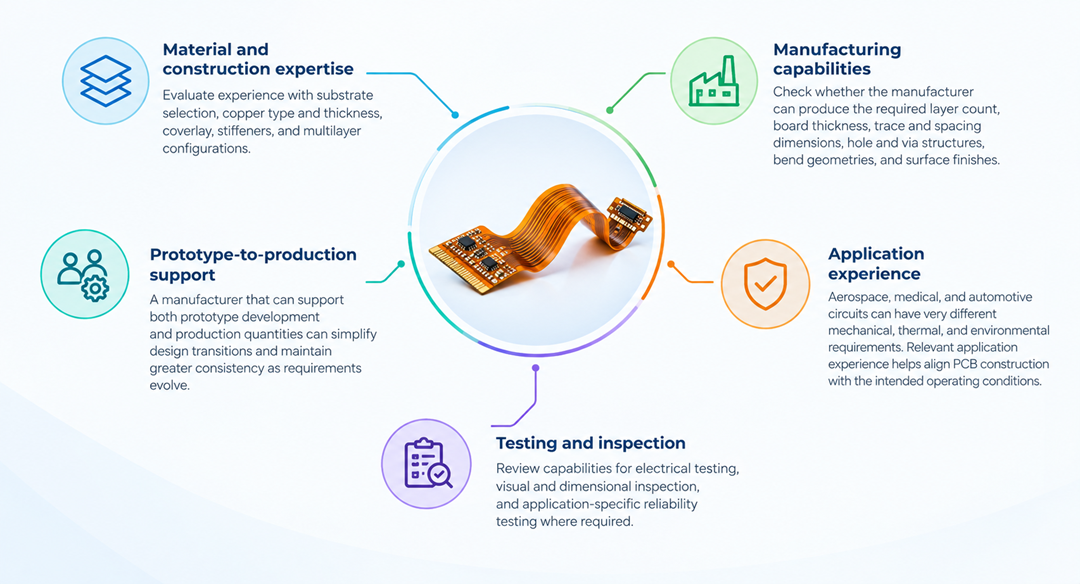
The manufacturer should be able to match the circuit’s construction and production requirements.
- Material and construction expertise: Evaluate experience with substrate selection, copper type and thickness, coverlay, stiffeners, and multilayer configurations. These choices directly affect flexibility, electrical performance, and durability.
- Manufacturing capabilities: Check whether the manufacturer can produce the required layer count, board thickness, trace and spacing dimensions, hole and via structures, bend geometries, and surface finishes.
- Application experience: Aerospace, medical, and automotive circuits can have very different mechanical, thermal, and environmental requirements. Relevant application experience can help align PCB construction with the intended operating conditions.
- PCB Testing and inspection: Review capabilities for electrical testing, visual and dimensional inspection, and application-specific reliability testing where required.
- Prototype-to-production support: A manufacturer that can support both prototype development and production quantities can simplify design transitions and maintain greater consistency as requirements evolve.
Why Consider Rigiflex for Application-Specific Flex PCB Manufacturing?
Rigiflex manufactures flexible and rigid-flex PCBs for aerospace, medical, automotive, military, telecom, and industrial applications. Our capabilities include multilayer construction, laser drilling and routing, fine trace and spacing, stiffeners, controlled impedance, and specialized material options. We also support quick-turn production with documented 1–5-day turnaround capabilities, along with AOI, flying-probe electrical testing, and netlist testing. Our manufacturing capabilities are supported by industry-recognized certifications and standards, including ISO 9001, AS9100, IPC-6013, UL, ITAR registration, and applicable MIL-PRF specifications.
Looking for a flex PCB manufacturer for your next aerospace, medical, or automotive application? Contact Rigiflex to discuss your requirements.
Frequently Asked Question (FAQs)
1. How are flexible PCBs manufactured for high-reliability applications?
Flexible PCBs for high-reliability applications use carefully selected materials, controlled fabrication processes, precise construction, protective coverlays and application-specific testing to ensure consistent electrical and mechanical performance under demanding operating conditions.
2. Why are flexible PCBs used in aerospace applications?
Flexible PCBs reduce weight, save space, and conform to complex geometries. They can replace wires and connectors while supporting compact aerospace electronics designed for demanding mechanical and environmental conditions.
3. How are aerospace flex PCBs manufactured?
Aerospace flex PCBs undergo material selection, circuit formation, drilling, plating, coverlay application, stiffener attachment, finishing, and testing. Manufacturing specifications depend on the application’s flexibility, weight, environmental, and reliability requirements.
4. Why are flexible PCBs used in medical electronics?
Flexible PCBs support compact medical electronics by conforming to complex shapes and reducing wiring and connectors. They enable lightweight, space-efficient designs while providing reliable electrical connections for application-specific requirements.
5. How are automotive flex PCBs manufactured?
Automotive flex PCBs are manufactured through circuit formation, drilling, plating, coverlay application, stiffener attachment, finishing, and testing. Material and construction choices depend on temperature, vibration, flexibility, space, and application requirements.