A rigid-flex construction brings together rigid and flexible sections, but each section must perform differently. The rigid areas require dimensional stability and support for components and interconnections, while the flex areas must withstand the specified bending conditions without degrading the circuit. These differences influence how the board must be constructed and which materials are appropriate for each section. Material selection can determine whether a rigid-flex PCB meets the demands placed on it throughout its service life. For engineers and designers, the goal is to match the material and construction to the board’s mechanical, electrical, thermal, and manufacturing requirements.
This post explains how to choose rigid-flex PCB material by covering flexible and rigid material options, flex construction, and common selection mistakes.
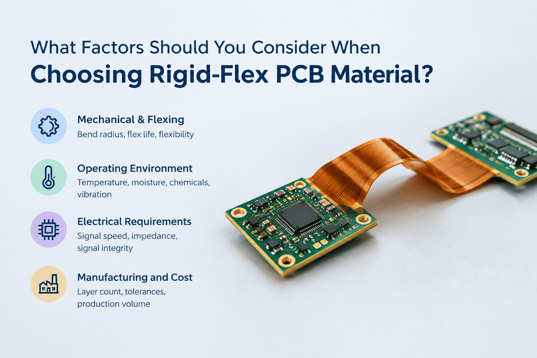
What Factors Should You Consider When Choosing Rigid-Flex PCB Material?
Material selection should begin with the conditions the PCB must meet during operation and fabrication. Consider the following factors before choosing a material. :
- Mechanical and Flexing Requirements: Determine how the flex section will behave during installation and operation. A static-flex application generally involves bending the circuit into position, while a dynamic-flex application subjects it to repeated movement. These requirements influence the selection of flex materials based on properties such as flexibility, thickness, and resistance to repeated mechanical strain. The required bend radius and cycle life should therefore be considered when selecting the material system.
- Operating Environment: The operating environment can place additional demands on the material system. Consider the expected temperature range and thermal cycling, along with exposure to moisture, humidity, chemicals, vibration, and mechanical shock. The selected materials should maintain their relevant mechanical, electrical, and dimensional properties throughout the expected service conditions.
- Electrical Requirements: Consider the PCB’s signal speed, operating frequency, controlled impedance, and signal-integrity requirements when selecting materials. For high-speed or high-frequency applications, electrical properties such as dielectric constant (Dk) and dissipation factor (Df) can influence signal behavior and transmission losses. Selecting materials with electrical properties suited to the application’s performance requirements can help support the intended impedance and signal-integrity targets.
- Manufacturing and Cost: The material combination must also be compatible with the intended fabrication process and board construction. Layer count, fabrication tolerances, available processes, and production volume can influence manufacturability and cost. The final selection should balance performance and reliability with manufacturability, production requirements, and cost.
Choosing the Right Flexible Material
Flex PCB materials must provide the mechanical, thermal, electrical, and dimensional properties required by the flexible section. Several materials are available for the flexible sections of rigid-flex PCBs.
The following are two commonly used options:
- Polyimide
Polyimide is widely used in flexible and rigid-flex circuits because it offers good thermal stability, dimensional stability, and mechanical durability. Its suitability for a specific design still depends on factors such as film thickness, copper type and thickness, bend radius, layer arrangement, and required flex life.
- Polyester (PET)
Polyester, or polyethylene terephthalate (PET), is a flexible substrate material valued for its dimensional stability, electrical insulation properties, and relatively low cost. It is commonly used in flexible circuits with less demanding thermal requirements. Compared with polyimide, PET has lower heat resistance and is less suitable for high-temperature fabrication and operating conditions, which can restrict its use in more demanding rigid-flex PCB applications.
Polyimide vs. PET: Which Flex PCB Material Is Right?
Polyimide offers a wider performance range and is generally the preferred option for demanding rigid-flex applications. PET can be appropriate where thermal exposure and mechanical demands are more limited. The following comparison provides a quick way to distinguish the two materials for initial selection:
| Selection Factor | Polyimide | PET |
| Temperature capability | Generally higher | Generally lower |
| Dynamic-flex suitability | Better suited | More limited |
| Dimensional stability | Generally higher | Generally lower |
| Material cost | Generally higher | Generally lower |
Choosing the Right Rigid Material Substrate & Material
The rigid sections require a laminate that provides the mechanical support and electrical properties needed by the board. Here are the commonly used material options for rigid sections of rigid-flex PCBs.
Standard FR-4
FR-4 is a widely used glass-reinforced epoxy laminate for rigid PCB sections. It provides a practical balance of mechanical strength, electrical performance, dimensional stability, and cost for many conventional designs.
Best suited for:
- General-purpose electronics
- Moderate thermal conditions
- Conventional digital and analog circuits
- Cost-sensitive designs with standard electrical requirements
High-Tg FR-4
High-Tg FR-4 has a higher glass-transition temperature than standard FR-4 grades, providing greater thermal stability during PCB processing and service. However, a higher Tg does not necessarily mean that the material can continuously operate at that temperature. Other thermal properties and the application’s operating conditions should also be considered when selecting the material.
Best suited for:
- Designs exposed to elevated temperatures
- Applications involving significant thermal cycling
- Assemblies with demanding thermal-processing conditions
- Designs where greater thermal stability is needed
High-Speed and Low-Loss Materials
High-speed and high-frequency designs may require specialized low-loss laminates when conventional FR-4 cannot meet the required signal-loss or signal-integrity targets. Low-loss laminates can reduce dielectric loss compared with conventional materials when the application demands tighter signal-integrity or insertion-loss performance. Material selection should be coordinated with the stackup and transmission-line geometry to meet the required impedance and signal-loss targets.
Best suited for:
- High-speed digital interfaces
- RF and microwave circuits
- High-frequency signal paths
- Designs with demanding signal-integrity or insertion-loss targets
Common Rigid-Flex PCB Material Selection Mistakes to Avoid
Material selection can become problematic when individual specifications are considered without evaluating the requirements of the complete PCB construction. Avoiding these common mistakes can help prevent unsuitable material choices, unnecessary design changes, and fabrication issues.
- Choosing Based Only on Cost: The lowest-cost option may not meet the board’s performance or fabrication requirements. Evaluate material cost alongside service conditions, construction requirements, and production needs.
- Ignoring Flex-Cycle Requirements: A flex construction suitable for a fixed bend may not withstand repeated movement. The required flex mode and cycle life should be established before selecting the material and construction.
- Treating Tg as the Operating-Temperature Limit: A higher glass-transition temperature does not define a laminate’s maximum service temperature. Other thermal properties and the actual operating conditions must also be considered.
- Overlooking Moisture Absorption: Some PCB materials absorb more moisture than others, which can affect dimensional stability, electrical performance, and reliability under humid conditions. Consider the expected operating environment and the material’s moisture-absorption characteristics before making a selection.
- Ignoring Electrical Properties: Selecting a material without considering dielectric constant (Dk) and dissipation factor (Df) can affect impedance control and signal performance, particularly in high-speed and high-frequency applications.
Final Selection of Rigid-Flex PCB Checklist
Before completing the rigid-flex PCB material selection process, confirm that the selected materials meet the design, performance, and fabrication requirements.
Here are the key factors to review before finalizing your material selection:
- Flex Mode and Cycle Life: The required flex mode and cycle life are defined.
- Bend Requirements: The bend radius and flex-section construction are established.
- Electrical Requirements: Electrical and impedance requirements are confirmed.
- Stackup and Material Compatibility: The complete stackup and compatibility between the selected materials have been reviewed.
- Fabrication Compatibility: The selected materials and their compatibility with the intended fabrication processes have been confirmed with the PCB manufacturer.
From Material Selection to PCB Fabrication
The right rigid-flex PCB material must work with the complete stackup, fabrication process, and intended service conditions. Rigiflex Technology manufactures rigid PCB, Flex PCB, and rigid-flex PCBs using material and construction options suited to different performance requirements.
Need help evaluating a rigid-flex PCB material or construction? Contact Rigiflex to discuss your requirements with its PCB manufacturing team.
Frequently Asked Questions
What is a coverlay in a rigid-flex PCB?
A coverlay is an insulating layer applied over exposed copper in the flex section. It protects the circuitry and provides electrical insulation.
What is the purpose of a stiffener in a flex PCB?
A stiffener reinforces selected areas of a flex circuit, such as connector or component-mounting areas. It adds local support without rigidizing the entire flex section.
What copper is best for dynamic flex applications?
Rolled-annealed (RA) copper is generally preferred because it offers better fatigue resistance during repeated bending.