Choosing the correct PCB connector affects much more than electrical connectivity. The right connector improves signal integrity, simplifies manufacturing, enhances product reliability, reduces maintenance costs, and ensures compatibility with the intended application. Understanding the different PCB connector types helps engineers design more reliable and efficient electronic products.
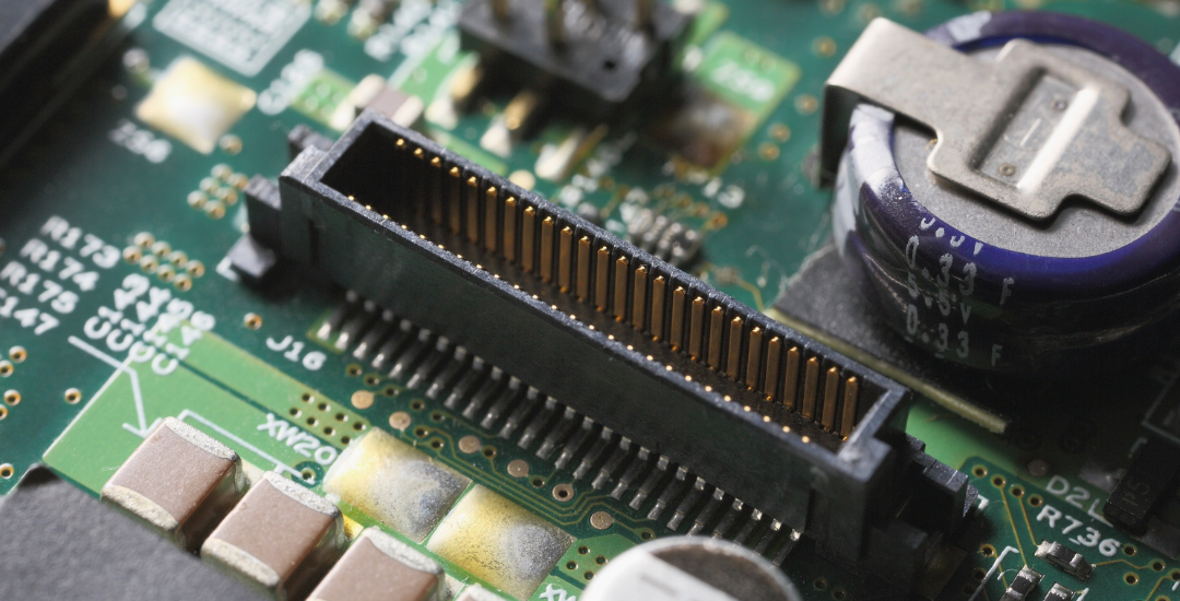
Types of PCB Connectors
PCB connectors are classified according to the type of electrical connection they establish within an assembly. Understanding these categories helps engineers select connectors that align with the electrical, mechanical, and environmental requirements of the intended application
1. Board-to-Board Connectors:
Board-to-board connectors establish direct electrical connections between two printed circuit boards without requiring external wiring. They reduce cable clutter, optimize space, and support modular product designs across a wide range of electronic applications. Here are the key types.
- Mezzanine Connectors: These connectors join two parallel PCBs in a stacked configuration, making them well suited for compact electronic assemblies where board space is limited.
- Stackable Connectors: They allow multiple PCBs to be vertically connected while maintaining a defined spacing between boards. They offer design flexibility and simplify future expansion or upgrades in modular electronic systems.
- Backplane Connectors: These connectors connect multiple daughterboards to a common backplane, enabling efficient communication and power distribution across an electronic system.
2. Wire-to-Board Connectors:
These connectors establish secure electrical connections between individual wires or wire harnesses and a PCB. They are widely used where external power or signal wiring must connect reliably to a PCB while allowing easy assembly and servicing. Common wire-to-board connector types include:
- Crimp Connectors: They secure a wire to a metal contact through mechanical compression before mating with a PCB connector housing.
- Insulation Displacement Connectors (IDC): IDC connectors establish electrical contact by piercing the wire insulation, eliminating the need for wire stripping, and reducing assembly time.
- Terminal Block Connectors: These connectors allow direct wire termination to a PCB using screw, spring-clamp, or pluggable terminal mechanisms.
3. Cable-to-Board Connectors:
Cable-to-board connectors provide a direct interface between cable assemblies and PCBs, enabling reliable transmission of power, signals, or data between internal components and external devices. They are commonly used in applications requiring organized cable routing and dependable electrical connections.
- Ribbon Cable Connectors: They terminate flat ribbon cables, allowing multiple conductors to connect to a PCB through a single interface.
- Circular Cable Connectors: As the name implies, they use a circular mating interface with multiple contacts to transmit power, signals, or data between cables and PCBs.
- D-Sub Connectors: They feature a D-shaped metal shell that provides proper mating orientation, mechanical stability, and EMI shielding while supporting reliable multi-pin signal transmission between PCBs and external devices.
4. Pin Header and Socket Connectors:
These connectors provide simple, cost-effective board-level interconnections by joining PCBs, modules, or cable assemblies through mating male and female contacts. The following are the most common pin header and socket connector types:
- Male Pin Headers: They consist of one or more rows of exposed metal pins mounted on a PCB. They are designed to mate with female headers or socket connectors, providing reliable electrical connections in development boards, embedded systems, and modular electronic assemblies.
- Female Headers: Female headers contain receptacle contacts that mate with male pin headers to create removable board-to-board or wire-to-board connections. They are commonly used where repeated assembly, servicing, or component replacement is required.
- Shrouded Headers: They provide secure and properly aligned board-to-board or wire-to-board connections. They incorporate an insulating housing around the pin contacts to ensure correct mating orientation, reduce the risk of mismating, and protect the pins from accidental damage
5. Universal Serial Bus (USB) Connectors:
USB connectors are standardized interfaces that support power delivery, data communication, and peripheral connectivity between printed circuit boards and external devices. Most common USB connector types include:
- USB Type-A Connectors: They provide standardized interfaces for connecting peripheral devices to host PCBs, enabling power delivery and data communication.
- Mini USB Connectors: They are designed for portable electronic products where board space is limited and moderate mechanical durability is required.
- Micro USB Connectors: Micro USB connectors are designed to provide power and data interfaces for portable electronic devices requiring a space-efficient connector footprint.
6. Radio Frequency (RF) and Coaxial Connectors:
RF and coaxial connectors are specialized PCB connectors designed to transmit high-frequency signals while maintaining controlled impedance and minimizing signal loss. They are used in wireless communication, RF testing, antennas, and high-frequency electronic systems. Most common RF and coaxial connector types include:
- SMA Connectors: SMA (SubMiniature Version A) connectors are threaded RF PCB connectors designed to provide secure, high-frequency signal connections with excellent impedance control.
- SMB Connectors: SMB (SubMiniature Version B) connectors are snap-on RF PCB connectors that provide quick connection and disconnection while supporting reliable high-frequency signal transmission.
- MCX Connectors: MCX (Micro Coaxial) connectors are compact RF PCB connectors that use a snap-on coupling mechanism to support high-frequency signal transmission in space-constrained electronic assemblies.
- BNC Connectors: BNC (Bayonet Neill–Concelman) connectors are RF PCB connectors featuring a bayonet locking mechanism that enables quick, secure mating for high-frequency signal transmission.
7. Power Connectors:
Power connectors deliver electrical power from external sources or internal distribution systems to PCBs and electronic assemblies. The most common power connector types include:
- Barrel Connectors: These connectors are cylindrical PCB power connectors designed to receive power from external DC power adapters.
- Molex Connectors: They are multi-pin PCB connectors designed to distribute power between PCBs, wire harnesses, and electronic components.
- JST Connectors: JST connectors are compact PCB connectors designed to provide reliable wire-to-board power and signal connections in space-constrained electronic assemblies.
8. High-speed Data Connectors:
These connectors support high-bandwidth data transmission while maintaining signal integrity and minimizing electromagnetic interference (EMI). The following are the most common high-speed data connector types:
- High-Definition Multimedia Interface (HDMI) Connectors: HDMI connectors provide standardized interfaces for transmitting uncompressed digital video and audio signals between printed circuit boards and external display devices.
- DisplayPort Connectors: DisplayPort connectors provide high-bandwidth digital video and audio interfaces for applications requiring high-resolution display connectivity.
Need Expert PCB Assembly for Your Next Project?
Choosing the right connector is only one part of building reliable electronics. At Rigiflex Technology, we provide precision PCB assembly services with expert support for connector integration, component placement, DFM review, and high-quality manufacturing. Whether you need prototypes or production volumes, our team helps deliver dependable electronic assemblies built for performance.
Frequently Asked Question (FAQs)
- Can the wrong PCB connector affect product reliability?
Yes, an incorrectly selected connector can lead to poor electrical contact, signal degradation, mechanical failure, or premature product failure. - What factors influence the lifespan of a PCB connector?
Connector lifespan depends on mating cycles, operating environment, electrical loading, material quality, and proper installation. - Can PCB connectors carry both power and signals?
Many connector families are designed to carry both power and signal lines within the same interface, provided they meet the required voltage, current, and signal-integrity specifications. - Why is connector compatibility important in PCB assembly?
Ensuring connector compatibility helps prevent assembly issues, improves electrical performance, and supports long-term product reliability.