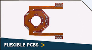
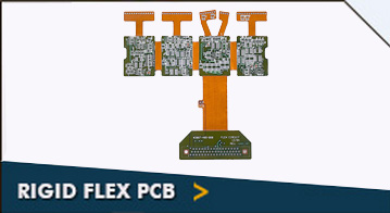
Rigiflex is one of the leading manufacturers of 14 layer rigid-flex PCBs. These PCBs are used for applications, which demand extreme precision and tight tolerances. Over the years, we have helped clients by designing and providing compact sized 14 layer rigid-flex PCBs. These circuit boards comprise flexible inner layers, which are attached using a prepeg film, which resembles to a multilayer flexible circuit. These rigid-flex PCBs are equipped with a board internally, externally, or both – as needed by the circuit.
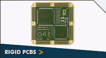
The rigid components of these circuit boards are utilized for high density device boards. Additionally, flexible circuits allow narrow lines, thereby supporting high density device population. The combination of rigid boards and flexible circuits allow us to offer streamline design, thereby reducing package weight and size.
Typically, these circuit boards are made from FR4 material. We can also provide them in exotic materials such as Rogers Ultralam 2000, Rogers RO4350, Arlon AR350, Nelco 4013, as well as several metal core materials. We use various types of stiffeners to bond flexible layers. They include stainless steel, FR4, polyimide, etc. We can provide 14 layer rigid-flex PCBs in minimum thickness 0.054ʺ and maximum thickness 0.250ʺ. The surface treatment is ENIG, whereas we also provide surface finishes like HASL – leaded and lead free solders, electroless soft gold, electrolytic nickel, immersion silver, carbon ink, etc. We use advanced laser machines, which enable us to deliver accuracy of mil traces, lines, and patterns. The 14 layer rigid-flex PCBs are used in applications such as telecommunication, computers, medical devices, and automobiles.
| 14 Layer Rigid-Flex |
| Specifications |
Technology |
|
|
| FR4 (Tg – 135C, 145C, 170C) |
| Rogers Ultralam 2000 |
| Rogers RO4350 |
| Rogers RO4003 |
| Polyimide |
| Teflon |
| Black FR4 |
| Arlon AR350 |
| Getek Copper Clad Thermal Substrates |
| Hybrid (Rogers and FR4) BT Epoxy |
| Nelco 4013 |
| Metal Core Materials |
|
|
|
| Thermo Set and PSA Based Aluminum |
| FR4 |
| Stainless Steel |
| Polymide |
|
|
|
| 2 Layer – Min .005″ Max .250″ |
| 4 Layer – Min .015″ Max .250″ |
| 6 Layer – Min .025″ Max .250″ |
| 8 Layer – Min .031″ Max .250″ |
| 10 Layer – Min .040″ Max .250″ |
| 12 Layer – Min .047” Max .250” |
| 14 Layer – Min .054″ Max .250″ |
| 16 Layer – Min .062″ Max .250″ |
| 18 Layer – Min .093″ Max .250″ |
| 20 Layer – Min .125″ Max .250″ |
| 22 Layer – Min .125″ Max .250″ |
| >24 Layer – Min .125″ Max .250″ |
|
|
|
Min .0025″ |
| Maximum PCB Size |
| 2 Layer 20″ x 28″ |
| Mulitlayer 16″ x 26″ |
|
| Minimum Conductor Space |
0.003″ |
| Minimum Conductor Width |
0.003″ |
| Minimum Drill Hole Size |
0.006″ |
| Finish Plating / Surface Finishes |
| HASL – Leaded Solder Tin/Nickel |
| HASL – Lead Free Solder |
| Electroless Soft Gold |
| Wire Bondable Soft Gold |
| Nickel Flash Gold |
| Electroless Nickel |
| Immersion Gold OSP |
| Electrolytic Nickel /Hard Gold and Selective Gold |
| Immersion Silver |
| Immersion Tin |
| Carbon Ink |
| ENIG |
|
| Finished Copper – Outer Layers |
| 1oz Cu – Min .004″ Trace/Space |
| 2oz Cu – Min .005″ Trace Space |
| 3oz Cu – Min .008″ Trace/Space |
| 4oz Cu – Min .010″ Trace/Space |
| 5oz Cu – Min .012″ Trace/Space |
|
| Finished Copper – Inner Layers |
| .5oz Cu – Min .004″ Trace/Space |
| 1oz Cu – Min .005″ Trace/Space |
| 2oz Cu – Min .006″ Trace/Space |
| 3oz Cu – Min .010″ Trace/Space |
| 4oz Cu – Min .012″ Trace/Space |
|
| Inner Layer Clearances |
| Min .008″ |
| Minimum Finished Hole Size |
| Final Thickness 062″ – .006” Hole Final Thickness .150″ – .014″ Hole |
| Final Thickness .093″ – .010″ Hole Final Thickness .200″ – .018″ Hole |
| Final Thickness .125″ – .012″ Hole Final Thickness .250″ – .020″ Hole |
|
| Gold Fingers |
| Per IPC-SM-840 |
| LPI Soldermask |
| Peelable Soldermask |
|
| Solder Mask Colors |
| Green/Green |
| Matte White |
| Black/Black |
| Matte Clear |
| Blue Top and Bottom Mix |
| Red One or Both Sides Mix |
|
| Silkscreen Type |
| Thermal Cure Epoxy Ink |
| LPI Ink |
|
| Silkscreen Colors |
| White |
| Black |
| Yellow Top and Bottom Mix |
| Red One or Both Sides Mix |
| Blue |
|
| CNC Functions |
| Scoring Edge to Edge Plated Counter bores |
| Skip Scoring – .250″ Spacing Milling |
| 30 or 60 Degree Score Angle Blind and Buried Vias |
| 30 to 100 Degree Countersink Controlled Z Axis Route |
| 15 to 45 Degree Gold Finger Bevel Castellated Barrels |
| Counterbores Offset or Recessed Beveling |
| Plated Countersinks |
|
| Other PCB Services |
| Blind and Buried Vias |
| Plated Slots Specified Dielectric |
| Tented Vias Controlled Impedance |
| Solder mask Plugged Vias Via Caps (Solder Mask) |
| Conductive Filled Vias |
|
| Quality / Testing |
| Inspect to IPC Class III Continuity Resistance – 10 to 20 Ohms |
| Net List Test per IPC-356D Isolation Resistance – 2 to 30 Megaohms |
| Test Voltage – 100 to 250 Volts Minimum SMT Pitch 0.5 mm |
|
| Tolerances |
| PTH Hole Size – +/- .002″ |
| Front to Back – +/- .002″ |
| NPTH Hole Size – +/- .001″ |
| Solder Mask – +/- .002″ |
| Tooling Holes – +/- .001″ |
| Hole to Pad – +/- .005″ |
|