LOGO
(714) 688-1500   pcboards@rigiflex.com

Flex & Rigid-Flex PCBs.. 1-5 Day Quick Turn

FLEXIBLE PCBS
RIGID-FLEX PCBS
RIGID PCBS

Superior & Trusted Flexible, Rigid-Flex & Rigid PCBs for Over 25 years

14 Layer Rigid-Flex PCB with Thermo Forming

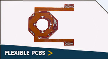
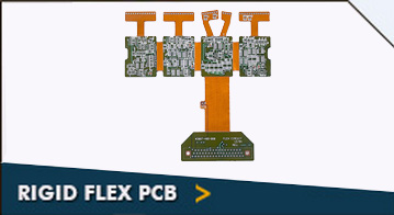
The design and manufacture of flexible printed circuit boards are never the same as before. With the rising demand for sophisticated electronic products, there has been a drastic change in the way rigid flex circuit boards are produced. There are several new innovations happening time and again, leading to the production of rigid flex printed circuit boards that guarantee better performance. We, at Rigiflex Technology, Inc., is at the forefront in all such innovations and major breakthroughs. We constantly learn and bring in flex circuit board with proven features. Our range of 14 layer rigid-flex pcb with thermo forming is also the result of several trials, experiments and hard work.

Distortion of RF signals is one of the main challenges in the wireless systems that are fitted with flexible circuit boards. This is due to the fact that wiring in these PCBs receive artificial signals, thereby acting as antennae. As the demand for compact, well-protected, and powerful systems is on rise, at Rigiflex, we provide PCBs with thermoformed shields that help minimize noise distortion, and ensure long-term performance. These shields are created using thermoforming technique. To accommodate shielding cans, our designers are grouping several components together.

As a leading flexible printed circuit board manufacturer, we keep quality as the top most priority. Due to our unwavering commitment to provide the finest products, we use only quality materials in the production of 14 layer rigid-flex pcb with thermo forming boards. The materials we use include FR4 (Tg – 135C, 145C, 170C), Rogers Ultralam 2000, RO4350, RO4003, Polyimide, Teflon, Black FR4, Arlon AR350, Nelco 4013, Metal Core Materials. The stiffeners used in its manufacturing include Thermo Set and PSA Based Aluminum, FR4, Stainless Steel and Polymide. 14 layer rigid-flex PCB with thermo forming boards can be surface treated utilizing the best of the methods as required by the customers, which helps add to their service life and resistance to outdoor extremities.

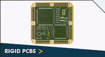
We being an experienced rigid printed circuit board manufacturer, own cutting-edge manufacturing facility, advanced equipment/systems, and right people that unitedly work to meet your project objectives. If you would like to know more about the technical capabilities of Rigiflex related to 14 layer rigid-flex PCB with thermo forming, please contact us at the earliest. We will work together throughout the production process, which in turn helps to manufacture the right rigid flex PCBs as specified earlier.

14 Layer Rigid-Flex
Specifications Technology
Board Materials
FR4 (Tg – 135C, 145C, 170C)
Rogers Ultralam 2000
Rogers RO4350
Rogers RO4003
Polyimide
Teflon
Black FR4
Arlon AR350
Getek Copper Clad Thermal Substrates
Hybrid (Rogers and FR4) BT Epoxy
Nelco 4013
Metal Core Materials
Stiffeners
Thermo Set and PSA Based Aluminum
FR4
Stainless Steel
Polymide
Final PCB Thickness
2 Layer – Min .005″ Max .250″
4 Layer – Min .015″ Max .250″
6 Layer – Min .025″ Max .250″
8 Layer – Min .031″ Max .250″
10 Layer – Min .040″ Max .250″
12 Layer – Min .047” Max .250”
14 Layer – Min .054″ Max .250″
16 Layer – Min .062″ Max .250″
18 Layer – Min .093″ Max .250″
20 Layer – Min .125″ Max .250″
22 Layer – Min .125″ Max .250″
>24 Layer – Min .125″ Max .250″
Core Thickness Min .0025″
Maximum PCB Size
2 Layer 20″ x 28″
Mulitlayer 16″ x 26″
Minimum Conductor Space 0.003″
Minimum Conductor Width 0.003″
Minimum Drill Hole Size 0.006″
Finish Plating / Surface Finishes
HASL – Leaded Solder Tin/Nickel
HASL – Lead Free Solder
Electroless Soft Gold
Wire Bondable Soft Gold
Nickel Flash Gold
Electroless Nickel
Immersion Gold OSP
Electrolytic Nickel /Hard Gold and Selective Gold
Immersion Silver
Immersion Tin
Carbon Ink
ENIG
Finished Copper – Outer Layers
1oz Cu – Min .004″ Trace/Space
2oz Cu – Min .005″ Trace Space
3oz Cu – Min .008″ Trace/Space
4oz Cu – Min .010″ Trace/Space
5oz Cu – Min .012″ Trace/Space
Finished Copper – Inner Layers
.5oz Cu – Min .004″ Trace/Space
1oz Cu – Min .005″ Trace/Space
2oz Cu – Min .006″ Trace/Space
3oz Cu – Min .010″ Trace/Space
4oz Cu – Min .012″ Trace/Space
Inner Layer Clearances
Min .008″
Minimum Finished Hole Size
Final Thickness 062″ – .006” Hole Final Thickness .150″ – .014″ Hole
Final Thickness .093″ – .010″ Hole Final Thickness .200″ – .018″ Hole
Final Thickness .125″ – .012″ Hole Final Thickness .250″ – .020″ Hole
Gold Fingers
Per IPC-SM-840
LPI Soldermask
Peelable Soldermask
Solder Mask Colors
Green/Green
Matte White
Black/Black
Matte Clear
Blue Top and Bottom Mix
Red One or Both Sides Mix
Silkscreen Type
Thermal Cure Epoxy Ink
LPI Ink
Silkscreen Colors
White
Black
Yellow Top and Bottom Mix
Red One or Both Sides Mix
Blue
CNC Functions
Scoring Edge to Edge Plated Counter bores
Skip Scoring – .250″ Spacing Milling
30 or 60 Degree Score Angle Blind and Buried Vias
30 to 100 Degree Countersink Controlled Z Axis Route
15 to 45 Degree Gold Finger Bevel Castellated Barrels
Counterbores Offset or Recessed Beveling
Plated Countersinks
Other PCB Services
Blind and Buried Vias
Plated Slots Specified Dielectric
Tented Vias Controlled Impedance
Solder mask Plugged Vias Via Caps (Solder Mask)
Conductive Filled Vias
Quality / Testing
Inspect to IPC Class III Continuity Resistance – 10 to 20 Ohms
Net List Test per IPC-356D Isolation Resistance – 2 to 30 Megaohms
Test Voltage – 100 to 250 Volts Minimum SMT Pitch 0.5 mm
Tolerances
PTH Hole Size – +/- .002″
Front to Back – +/- .002″
NPTH Hole Size – +/- .001″
Solder Mask – +/- .002″
Tooling Holes – +/- .001″
Hole to Pad – +/- .005″

Quick Contact

All Fields are Mandatory (*)

Capcha

Fourbox

Need it quick? That is our speciality!